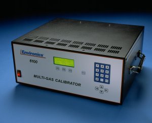
The Environics Series 6100 Multi-gas Calibrator was designed to be the finest instrument available for producing highly precise mixtures of ozone and other gases. The Series 6100 automatically performs zero, precision, span and multi-point calibrations using NO, NO2, SO2, CO, 03, hydrocarbons and other gases of interest. The 6100 meets all U.S. Environmental Protection Agency requirements. The system consists of a single chassis supporting 2 thermal mass flow controllers (optional third MFC available) , an ozone generation module, a mixing zone, a reaction chamber for gas phase titration, and control electronics. Commands are entered from the front panel and displayed on a backlit 4 line by 20 character liquid crystal display. The instrument may also be remotely operated using contact closures or the RS-232 serial data interface, both are standard in the Series 6100.
The Series 6103 consists of a single chassis supporting up to 3 thermal mass flow controllers, an ozone generation module, photometer, glass output manifold, mixing chamber, a reaction chamber for gas phase titration, and control electronics.The internal ultra-violet (UV) based ozone generator is temperature controlled and includes a precision photo-optical feedback circuit to compensate for lamp aging effects providing stable ozone generation. The ozone generator is factory calibrated using a NIST traceable photometer standard
Over the next weeks, we are going to review some common questions on troubleshooting the Series 6100 and 6103. The full user and service manuals can be found here. Some of these guides, such as today’s, will apply to both units while others are specific to the Series 6100 or Series 6103. We will clearly note when this is the case.
Let us know if you have a specific issue you’d like us to cover!
Note: Customers who work on their units accept the risks of working on machinery and are responsible for taking all proper safety precautions. If in doubt, contact our service department!
System display does not come up – Series 6100 and 6103
- Check to see if the switch is illuminated. If it IS NOT illuminated,check your power cord connection and the power source voltage. We suggest the use of a power conditioner. You should also check fuses in power entry moduleon rear panel and replace if necessary.
- If the switch IS illuminated,
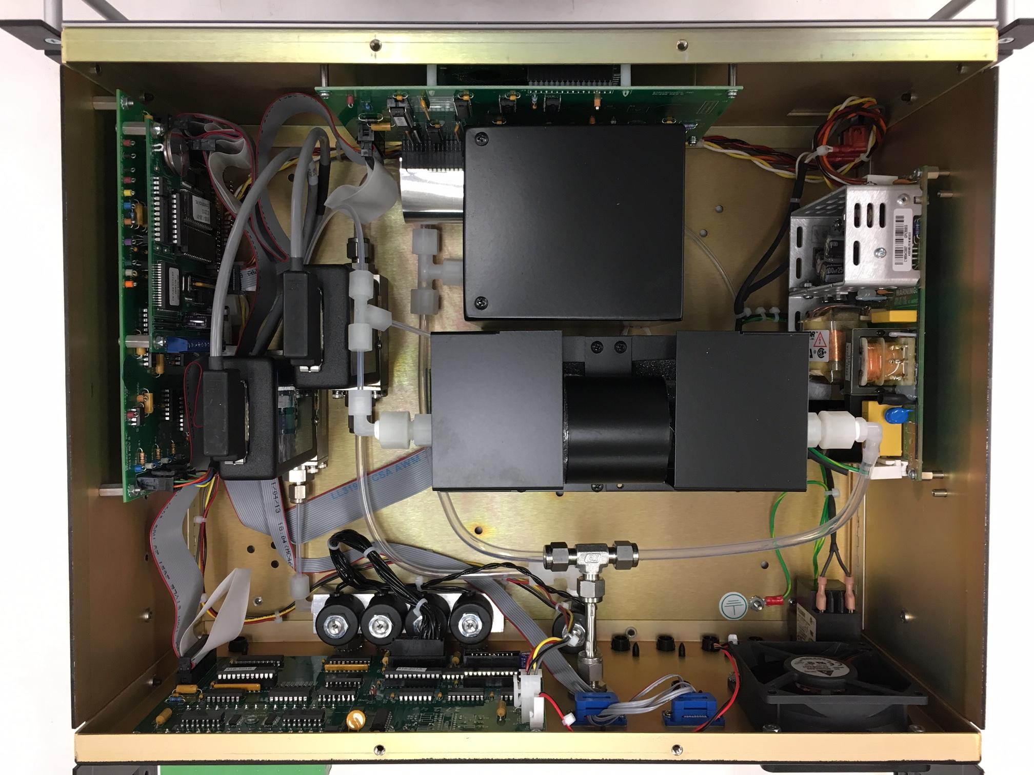
- Check that all cables and connections are secure. A loose cable to the PC406 can cause the display to not come up.
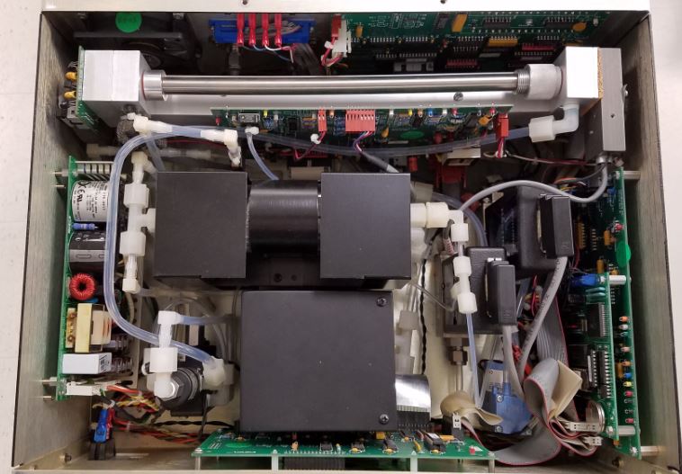
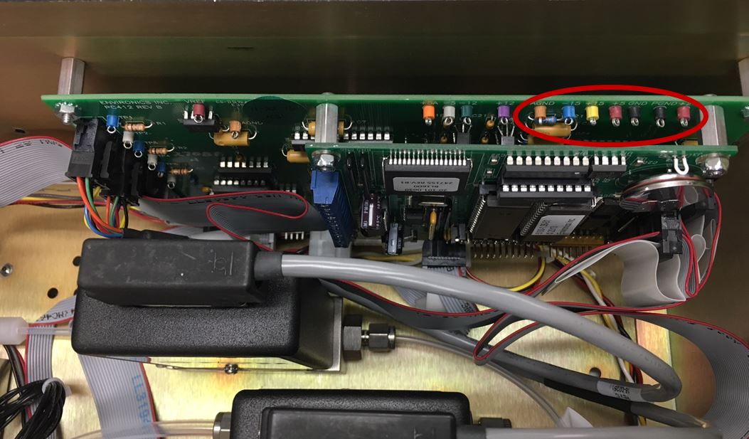
- Once you verify the cables are making good connection, you will want to check the steady state test points located on the PC412-1D. This is the rear board of the sandwiched boards on the right side of the chassis.
- Check TP14, (-15VDC), TP15 (+15VDC), TP16 (+5VDC) (all using TP17 for GND) and TP19 (+24VDC) (using TP18 for GND). These are all labeled within the circled area on the PC412.
- If any of these are absent, check the power supply voltages with the power cable disconnected from PC412 using the below diagram as your guide.
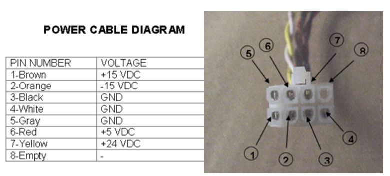
- An absence of any of these power supply voltages suggests the need for a new power supply.
- If all power supply voltages are present, the issue is within another PCB or component and these will need further testing to identify the problem.
Next time we will cover what to do if you are getting low or no flow from one or more of your MFCs! Subscribe to the blog (look up and on the right) so you don’t miss a thing!