Today, is Part 2 in our series on some of the common questions on troubleshooting the Series 6100. The full user and service manuals can be found here.
Part 1 looked at what to do if your display does not come up. Today we will focus on your flow and MFCs.
As with Part 1, these issues are dealt with in the same manner with a Series 6100 and a Series 6103.
Let us know if you have a specific issue you’d like us to cover!
Note: Customers who work on their units accept the risks of working on machinery and are responsible for taking all proper safety precautions. If in doubt, contact our service department!
Zero or low flow from one or more MFC
Begin by making sure your gas is hooked up to the correct input port/s. Check and adjust input pressures if necessary. Nominal pressure is 25 PSIG. Tube size for MFC1 should be ¼” O.D. minimum, 1/8” minimum for MFC2.
Once you have confirmed your input is correct, if the problem continues, remove all output connections to the system and try again. This will insure that the problem is not back pressure related.
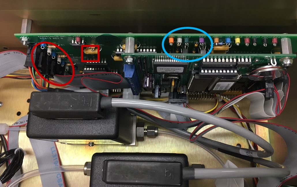
Now that you have eliminated issues with the processing as well as at the input and output, you should check the power. Check out Part 1 of our series on the details of this testing. In addition to those test points,TP9(+5A), TP10(-5), TP11(-12) and TP12(+12) should be checked (the blue circle below). These steady state VDCs are used by the MFC ADC and DAC.
Assuming your power is not the issue, we now will look at the MFC itself.
-
- In Flow mode, request the span of the MFC (100% point).Measure the command voltage to the MFC on the PC412 (see above). This will be TP1, TP3 or TP5 (blue TPs from top to bottom in the red circled area) depending on if you are monitoring MFC1, MFC2 or MFC3 respectively. TP8 is the brown analog ground test point for negative (black) meter lead, shown in the squared area above.
- If your command voltage is approximately +5V, measure corresponding MFC response test point on the PC412. This will be TP2, TP4 or TP6 (white TPs for MFC1-MFC3 from top to bottom in the red circled area above). Again, use TP8 as your ground. The response voltage should be very close to the command voltage.
- If the command and response voltage are both okay, it might be that the actual flow is just not being displayed. This could be caused by corrupt memory, which can often be resolved by removing the memory chip, waiting a minute or two, reinstalling and the initializing the unit.
- If the command is good but response voltage is low or 0, there may either be a problem with the MFC cable or the MFC. Try swapping the MFC cable and repeating the test. If these things fail to fix the problem, the issue is most likely the MFC itself. You should contact us for assistance in getting this resolved.
- If your command voltage is NOT +5V, check the the MFC size setup. Press in the keys in this order to reach the service menu: 9 F1 F2 F3 Menu. Arrow down to “Set MFC Size” and verify this matches your unit setup. You should also verify the calibration data for the MFC in the system mode to ensure that the values have not been changed since the last calibration. Environics sends a hardcopy of all data for reference. Contact us if you need them resent.
- If your command voltage is NOT +5V and you setup is correct, you most likely have an issue in the A194 assembly which contains the PC401 and PC412. You should contact us for assistance in getting this resolved.
As always, we are here to answer any questions or concerns!
Next time we will cover what to do if you are getting unstable flow from one or more of your MFCs! Subscribe to the blog (look up and on the right) so you don’t miss a thing!