The Environics® Model 4000 are a trio of units that can automatically mixes up to seven individual gases in a balance gas or dilute up to 10,000:1 (or higher, dependent on your setup). The gas mixes can be used in generating precise gas calibration standards, creating gaseous atmospheres or producing gas mixes for analytical research or production purposes. The units can produce gas concentrations from percent to ppb levels for single or multi-point calibration, allowing you to use fewer cylinders.
All 4000/4040/4020 consists of two components: the instrument and the user’s personal computer. The user interface is a Microsoft® Windows application that communicates with the Environics system via a USB (now standard) or RS232 serial interface. Check out of video series on using the Windows 7/8/10 software.
Last time we looked at issues with communication. Today, we will troubleshoot low/no flow issues with one or more mass flow controllers (MFCs).
Zero or low flow from one or more MFCs
Note: There are two versions of the Series 4000/4040/4020. You confirm which version you have by checking the order or the serial number label on the rear of the unit. 4000/4040/4020 are the original revision, have a PC401 and PC402 board and have RS232 standard. N4000/N4020/N4040, which have USB standard, are the more recent revision and have a single board, the PC405.
- Begin by making sure your gas is hooked up to the correct input port/s. Check and adjust input pressures if necessary. Nominal pressure is 25 PSIG.
- Once you have confirmed your input is correct, if the problem continues, remove all output connections to the system and try again. This will insure that the problem is not back pressure related.
- If the green status light is not blinking, this suggests a power issue. This can be confirmed (since it is possible the light is just burnt out) by checking the power test points as outlined in our previous troubleshooting post.
- It is critical to be sure the setup and calibration tables in the system are correct. We would recommend you reinitialize the system to make sure that all of the setup is correct for the unit. It is a quick process and is outlined in this Technical Bulletin. Once you run this process, you can try to flow again and see if the problem is corrected.
- If you are still seeing an issue, remove the cover of the unit and verify all of the MFC cables are securely latched.
- If you are still no seeing flow, you can run the problem MFC in the calibration mode to see if the problem exists there as well. This will insure that the problem is not related to any issues with cylinder or program setup. In our latest software, this is done by clicking the Instruments button and then the Calibration tab. For each MFC, click on the 100% calibration point and then click Start.
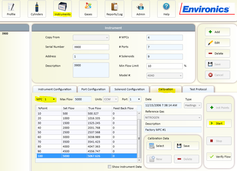
While flowing, you can measure the command and response voltages of the MFC on the PC402 or PC405 (see below).
For the PC402 – This will be the odd test points (TPs) in the red area from top to bottom for MFC1 through MFC4 respectively. TP2 is the brown analog ground test point shown in the black squared area.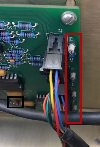
For the PC405 – This will be the odd TPs in the red area from right to left for MFC1 through MFC8 respectively. TP6 is the brown analog ground test point for negative (black) meter lead, shown in the black squared area.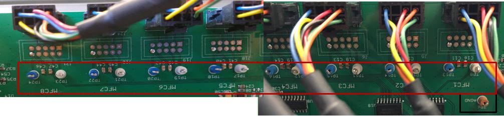
1. If your command voltage is approximately +5V, measure corresponding MFC response test point. The response voltage should be very close to the command voltage (~5V).
For the PC402 – This will be the even TPs in the red area from top to bottom for MFC1 through MFC4 respectively. TP2 is the brown analog ground test point shown in the black squared area.
For the PC405 – This will be the even TPs in the red area from right to left for MFC1 through MFC8 respectively. TP6 is the brown analog ground test point for negative (black) meter lead, shown in the black squared area.
2. If the command is good but response voltage is low or 0, there may either be a problem with the MFC cable or the MFC. Try swapping the MFC cable and repeating the test. If these things fail to fix the problem, the issue is most likely the MFC itself. It could be that the solenoid is not opening properly. You should contact us for assistance in getting this resolved.
3. If your command voltage is NOT +5V and you setup is correct, you most likely have an issue in the PC401/PC402 or PC405. You should contact us for assistance in getting this resolved.
As always, we are here to answer any questions or concerns!
Subscribe to the blog (look up and on the right) so you don’t miss a thing!