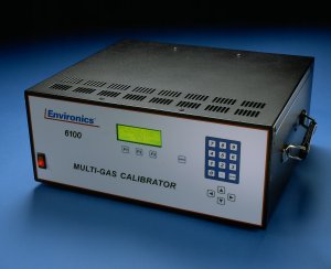
Today, is Part 8 in our series on some of the common questions on troubleshooting the Series 6100 and S6103. The full user and service manuals can be found here.
Part 1 looked at what to do if your display does not come up, while Part 2 and Part 3 focused on what to do if you are seeing issues with flow. Part 4 looked at what to do when you were not getting any ozone regardless of the command. Part 5 and Part 6 looked at a variety of ozone issues in the Series 6100 specifically, while Part 7 looked at ozone issues with the Series 6103.
Today, we will look at how to troubleshoot photometer issues in a Series 6103.
Let us know if you have a specific issue you’d like us to cover!
Note!!: Customers who work on their units accept the risks of working on machinery and are responsible for taking all proper safety precautions. If in doubt, contact our service department! NEVER unplug the ozone or photometer lamps while the unit is powered on. This can damage the circuitry.
System built after 11/2002 use a chassis with hinged side panels. This allows the side panels to be dropped for troubleshooting purposes. The cable lengths will allow the system to be powered on while the panels are dropped. However, always power down before dropping the panels.
No Ozone Detected by the Photometer
First, check that all of the photometer calibration data is properly entered in the System setup.
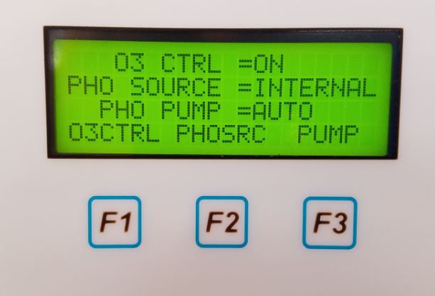
Make sure that whatever ozone source you are using, whether internal or external, is producing ozone properly and that you have set the unit to read ozone in the external or internal respectively. This can be set by pressing the Menu bottom while in PHOTO/CONC/FLOW modes and using F2 to toggle.
Next check that the photometer lamp is illuminated. When in photometer mode, if the intensity of the lamp (displayed on the top line) are at or neat zero, your lamp is not on. This could be due to the lamp itself, or an issue with the PC414 or PC415. If a spare lamp is available, you can eliminate the lamp as the source of the problem by swapping them. BE SURE to never power on the unit without a lamp plugged into the PC415. When replacing the lamp, be sure it is backed out slightly to allow for expansion. If the issue is a board, contact us for assistance in repairing or replacing the board.
If your lamp is properly illuminated, check to make sure the pump is enabled and running (for a detailed how to, check out Part 7 of our series here)
If you are in photometer mode and are trying to read external source of ozone,make sure the vented source of ozone is connected to the SAMPLE IN port and zero air is connected to REFERENCE port at 25 PSIG.
Verify that the pump is enabled and running (for a how to, check out Part 7 here).
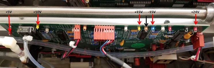
Check all steady state test points on PC415 are as below (ground = black arrow).
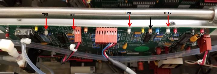
 In addition, the following TPs should be as follows:
- TP5 and 6: gas pressure and temp – approximately 2.45V (for 14.7 PSIA)
- TP8: block heater – between 4-5 volts (for temp between 25-50oC)
- TP12: block temperature – after warm up, between 4.9-5.1V (49-51oC)
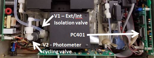
The final step to troubleshoot is that the photometer valve V1 or V2 is functioning.With the system power off, disconnect solenoid valve connector between PC401 and V2. Measure the DC resistance of V2. The resistance should be approximately 80 ohms. If resistance is good, PC401 high current driver circuit may be bad or solenoid valve plunger is stuck. We suggest you return the unit for evaluation and tuneup.
As always, we are happy to assist.
If you need further assistance or to order replacement parts, Contact us!
Next time we will wrap up this series with some additional photometer troubleshooting! Subscribe above so you don’t miss a thing!